Can I snap to a grid while using the Pull or Move tool?
Yes. In the Solids group in the Snap screen in SpaceClaim Options, you can change snap options for both incremental or objects settings.
How and why should I use the Groups feature?
Use groups to define a set of selected objects or to setup driving dimensions.
- Select a set of objects and click Create Group in the Groups panel to save the selection for future use.
- Create a ruler dimension in the Pull or Move tool and click Create Group to save that dimension as a driving dimension.
How can I create a surface patch?
Use the Patch blend option within the Fill tool in the Edit group on the Design tab. You can select faces and the Fill tool will automatically create a patch if you also select at least one edge. For more information, refer to the SpaceClaim Online Help.
How can I dimension my model while still in the design process, without moving to a drawing sheet?
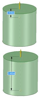
First, determine if you are dimensioning the model to indicate size and proportion or, if you want to drive changes to the model with dimensions. Both scenarios are described below. Changes to a model are done with tools that use dimensions to define the size of a change. Usually dimensions appear on screen when using a tool to make an edit. For example, when using the Pull tool to change the height of a cylinder, a dimension appears that shows the size of the change:
To create a dimension that measures the height of the cylinder, click the Ruler icon in the Options panel or on the mini-toolbar. Click the bottom of the cylinder to create a temporary dimension that measures the height.Creating dimensions for reference is done with SpaceClaim Annotation tools. Use the Dimension tool on the Detail tab to create dimensions that measure length, angle, and other characteristics. Annotation dimensions can also be used to drive model changes. For more information, refer to the SpaceClaim Online Help.
How can I render my model?
SpaceClaim Engineer includes KeyShot Lite. Additional rendering capabilities can be added with the KeyShot HD or KeyShot Pro options. For more information, please contact the SpaceClaim Sales Team at
sales@spaceclaim.com to arrange for a free trial.
How can I specify a shape for the new surface I create using the Patch Fill tool?
Patch Blend in the Fill tool uses faces, curves, and points as input when creating a surface patch. The created patch attempts to fit through selected faces, curves, or points. For more information, refer to the SpaceClaim Online Help.
How do I constrain my sketch?
Sketches are not constrained in SpaceClaim because they are not intended to persist. Create a sketch to the correct dimensions, turn it into a surface, and then use the Pull tool to pull it into a solid. For best results, make edits to the resulting solid rather than editing the sketch. For more information, refer to the SpaceClaim Online Help.
How do I create a fillet?
A
fillet is a
round in SpaceClaim.
To create a round - Click the Pull tool in the Edit group on the Design tab.
- Select the edge or edges you want to round.
- Select the Round option in the Options panel or from the mini-toolbar.
- Click and drag the edge in the direction of the Pull arrow.
For more information, refer to the SpaceClaim Online Help.
How do I create a helical revolve?
To create a helical revolve - Select the Pull tool.
- Select the face or edge you want to revolve.
- Alt+select a line or an axis to revolve about.
- Click the Revolve helix option in the Options panel and enter dimensions for the helix.
For more information, refer to the SpaceClaim Online Help. To view a video tutorial on helical revolve go to
http://www.spaceclaim.com/Support/Tutorials/SpaceClaim_TipsTricks.aspx?t=19
How do I create a pattern?
To create a pattern - Click Move in the Edit group of the Design tab.
- Select the Create patterns checkbox in the Options -Move panel.
- Select a protrusion, depression, sketch, points, axes, planes, origins, or 3D curves to be the first member of the pattern.
- Drag a move handle to copy the first pattern member to the location of the last member of the linear pattern.
- Type a new value for the pattern count.
- Press Tab to change the distance or spacing.
For more information, refer to the SpaceClaim Online Help.
How do I create a rotational pattern?
To create a rotational pattern - Select the geometry you want to pattern.
- Click the Move tool.
- Select the Create Pattern checkbox in the Options panel.
- Anchor your move tool to the center point you want to pattern around.
- Rotate the Move tool to create your pattern.
For more information, refer to the SpaceClaim Online Help.
How do I dimension my model?
To create dimensions for annotating a part, use the Dimension tool in the Annotation group on the Detailing tab.
- All dimensions are placed on an annotation plane in design mode, which you can toggle on or off for display purposes.
- Dimensions display on the drawing sheet (if you are dimensioning a model in a drawing sheet).
- You can use the Ruler option in the Pull or Move tool to create temporary dimensions while editing a part. You can save these dimensions by creating a group in the Groups panel. These dimensions can then be used to drive changes with the Pull or Move tool.
For more information, refer to the SpaceClaim Online Help.
How do I get back to my sketch?
SpaceClaim does not save sketches for future edit. Once you create a solid from a sketch, SpaceClaim recommends that you use the Pull and Move tools to edit the solid instead of editing the sketch.
How do I loft surfaces?
SpaceClaim uses the term
blend instead of
loft.
To blend surfaces - Click the Pull tool in the Edit group on the Design tab.
- Click the Blend option in the Options window.
For more information, refer to the SpaceClaim Online Help.
How do I make assembly models?
You make assembly models by placing each solid in a component. Simply right click on a solid in the Structure tree and select Move to New Component, and then name the component. Components can take on assembly conditions, whereas solids by themselves cannot have assembly conditions. With click and drag, components can be rearranged to reflect any desired assembly structure.
How do I package multiple components into one assembly to send to a client?
In order to send a client an assembly model properly, you need to make sure that all your components have been internalized. Click on a component in the Structure tree with the right mouse button and select Use Internal Copy to make it internal. Finally, save your assembly and send the resulting SpaceClaim document to the client.
How do I use the Wrap around target option in the Project tool?
The Wrap around target tool allows you to take planar curves or text and wrap them onto planes, cylinders, and cones. You may choose a surface target or establish a direction for the wrap. Curves can be wrapped onto geometry with per-existing imprinted wrapped curves. Surfaces may be used for wrapping, however only the surface edges are used to wrap around the target.
To wrap a curve, text, or a surface around a target object:
- Click the Project tool
- Check ON the Wrap around target option
- Click the curve, text or surface you want to wrap
- Click the Select Direction tool guide and choose a direction, you will see purple lines on the target as a preview
- Click the Complete tool guide or press the Enter key

What does Style Painter do?
Style Painter paints display properties from one object to another. The tool applies color and transparency intelligently from one object type to a different object type, for example, you can copy body colors and textures between geometry or font styles between notes and annotations.
What does the Rounds tool on the Prepare tab do?
Use the Rounds tool on the Prepare tab to remove rounds from a model.
For more information, refer to the SpaceClaim Online Help.
What is the difference between the Mirror tool in Sketch mode versus 3D mode?
You can use the Mirror tool to mirror bodies, faces, and sketch curves. The Mirror tool can be used in Sketch mode or in 3D mode. In Sketch mode, you can also create a mirror line: draw a line and select Set as Mirror Line from the right mouse button context menu. If there is a mirror line in your current sketch plane, all new sketches will mirror across the line. In addition, if you make a change to a mirrored curve in the sketch plane it will modify the curve and its mirror.
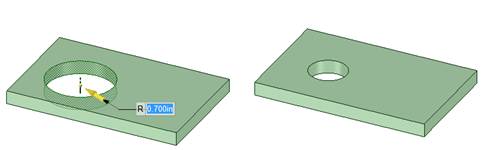
What´s the difference between Pull and Move?
In the simplest sense,
Pull creates or extrudes, and
Move translates or rotates. For example, if you pull a hole, the
size of the hole changes:
But if you move the hole, the
location of the hole changes:
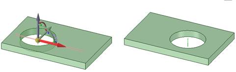
Only in the case of Pulling or Moving a planar face is the behavior similar.
When I try to pull multiple faces, why do I get surfaces instead?
This may occur if you continue to hold the Ctrl key. Try the following:
- Hold the Ctrl key to make a copy of a face as you drag.
- Hold the Ctrl key to select multiple faces, and then release the Ctrl key before using the Pull or Move tools.
Where do I preform Boolean operations?
Use the Combine tool in the Intersect group on the Design tab to perform Boolean operations. For more information, refer to the SpaceClaim Online Help.
Why are solids grayed out in the design window?
The solids may not be included in an active component. To activate the document level component, click the right mouse button on the top level component and choose Activate Component.
Why can´t I combine a solid with a surface?
The surface must extend through the solid. Use the Pull tool to extend the surface until it fully intersects the solid.
Why does a face change in size when I pull it?
Most likely you are pulling on a face without also selecting its neighboring edges. Try selecting the edges along with a face and then pull. The face stays the same size and extrudes that geometry. By default SpaceClaim uses the adjacent faces to influence how to pull a face.
Why does my solid turn into a surface when I hit the Delete key?
The Delete key removes geometry from a model. If you delete a face, the solid turns into a surface with a hole where the face used to be. In this scenario, SpaceClaim recommends that you use the Undo tool to return your design to the solid state. If this is not possible, the Missing face tool in the Fix group on the Repair tab can help you search for holes in the model and will attempt to patch over them.
Why does one solid in an assembly automatically move every instance of that component throughout the assembly?
If you have multiple placements of the same part (component containing a solid) in an assembly, also referred to as an
instance, they will all share the same geometry. If you select a solid in one instance and move it, it is considered changing the geometry and the solid will move in each instance. You should select a single component in the structure tree and move it only if you want to change the location of that instance.
Why won´t solids combine together?
The operation may fail because of errors in the body geometry. You must remove the bad geometry before attempting to combine solids. Select the solids, and then select Check Geometry in the Inspect group of the Measure tab to identify any bad geometry.